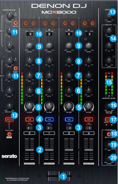
CROSSFADER. Blends audio between the channels assigned to the left and right side of the crossfader.
VOLUME. Volume Faders (mixer channel order is 3-1-2-4 decks). Note that the faders will not to alter the sound of the corresponding software deck, if the PC-LINE switchers are on LINE or ENGINE positions, and the sound of the software decks will be muted. Hold SHIFT down and then use the Volume Faders to start/stop the deck when moving from the minimum to any other position (Fader Start/Stop)
CF ASSIGN. Use these switchers to assign each mixer channel to a side of the Crossfader. Select the L (Left) or R (Right) position to assign a deck to the left or right side of the crossfader. When in Thru position, the crossfader will not affect the output level of the mixer channel.
CUE/PFL. Use these buttons to send one or more channel's pre-fader signal to the Cue Channel for monitoring. When engaged, the buttons will be lit (orange for decks 3 and 4 and blue for decks 1 and 2).
FILTER. Applies a High/Low-pass Filter on each channel.
EQ LOW *. Adjusts low (bass) frequencies of the corresponding channel in the software or hardware Input.
EQ MID *. Adjusts the middle (mid) frequencies of the corresponding channel in the software or hardware Input.
EQ HI *. Adjusts the high (treble) frequencies of the corresponding channel in the software or hardware Input.
LEVEL. Adjusts the audio level (gain) of the corresponding channel in the software or hardware Input.
INPUT SELECTOR. Set this switch to the desired audio source for each mixer channel: - PC (a track playing on that layer in VirtualDJ), Set all 4 switches to PC position in order to control 4 VirtualDJ decks. - LN1/2/3/4 (a device connected to the Line Inputs on MCX8000 rear panel). - ENGINE (available for Channels 1 and 2) Track playing from the USB 1/2 Source using the Engine software. Note: the software deck will be muted if the switcher is on LINE or ENGINE positions.
MIC1/MIC2. Adjusts the Level, High and Low frequencies of each Microphone Input (connections at the rear panel). Use the ECHO button to apply an Echo effect to the each one of the Microphone signals. This section is completely working on the Hardware side, so there is no feedback to the software, and the Microphone Inputs are not part of the USB Audio interface either.
MIC ECHO/ON/POST. Use the MIC ECHO knob to adjust the amount of the Echo effect applied on both the Microphone signals. Use the MIC ON button to turn on/off both Microphone inputs. Use the TALKOVER button to automatically reduce the Master Output level when signal is detected on the Microphone inputs. Hold SHIFT and then use the same button (POST) to output the Microphone Input signals to the Booth Output only.
MASTER LEVEL Adjusts the output level of the Master Output (connection at the rear panel). Independent Hardware operation, not controlling VirtualDJ Master Output nor its movement is visible on VirtualDJ GUI
BOOTH LEVEL/HI/LOW Adjusts the output level of the Booth Output (connection at the rear panel) and apply Hi/Low Equalizer adjustments. Independent Hardware operations, not controlling VirtualDJ mixer nor their movements are visible on VirtualDJ GUI
MASTER VU METER Indicate the output level of the Master Output. Independent Hardware operation, not reflecting VirtualDJ Master VU Meter of VirtualDJ GUI
SAMPLER VOLUME Adjust the Master Volume of the VirtualDJ Sampler
XF-LINK Use this button to Link/Un-Link Video Crossfader with Audio crossfader. When the green LED is turned on, the Video Crossfader will follow the position of the Audio Crossfader (Linked). Hold SHIFT and then use the same button to disable the Audio Crossfader (Video Crossfader will still be controlled by the X-Fader if the green LED is turned on. The red LED will be off f the Audio Crossfader is disabled.
SPLIT CUEUse this button to send Master Output signal to one side of the Headphones and the CUE/PFL channels to the other one. Independent Hardware operation, not controlling VirtualDJ Split Cue setting
PHONES MIX Use this knob to blend Master Output signal with the Channels that have the CUE/PFL buttons enabled. When the knob is at the minimum position, only audio coming from the channels that have CUE/PFL enabled will be sent to Headphones. When in maximum position only audio signal from Master Output will be sent to the Headphones channel. Independent Hardware operation, not controlling VirtualDJ Headphones Volume knob nor its movement is visible on VirtualDJ GUI
PHONES LEVEL Adjust the Volume of the Headphones Channel. Independent Hardware operation, not controlling VirtualDJ Headphones Mix knob nor its movement is visible on VirtualDJ GUI
* Note: The device is offering Full Stems controls. See details at EQ Modes