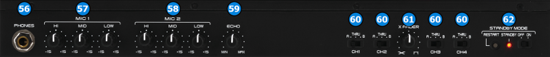
MIC 1 EQ: Adjust the EQ for MIC1 input (Hardware operation, not visible on the VirtualDJ GUI).
MIC 2 EQ: Adjust the EQ for MIC2 input (Hardware operation, not visible on the VirtualDJ GUI).
ECHO STRENGTH: Adjusts the amount of ECHO effect applied on MIC inputs. (Hardware operation, not visible on the VirtualDJ GUI).
CROSSFADER CH ASSIGN: Define if a mixer channel will be output regardless of the position of the crossfader (THRU position) or Left/Right.
CROSSFADER CURVE ADJUST: Adjusts the curve of the crossfader.
STANDBY MODE CONTROL: Control whether the unit will enter automatically to standby mode / Wake up the device when it's on standby mode. Please refer to unit's manual for further information.
Rear
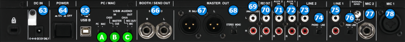
DC INPUT: Connect the supplied PSU.
POWER SWITCH: Turns on/off the power on the device. Please turn on the device only after doing and securing all connections on the back.
USB CONNECTOR: Use a standard USB cable to connect MC-6000 with your computer.
BOOTH OUT: Booth signal output (TRS – Balanced). The strength of the signal is controlled by “BOOTH/SEND LEVEL” knob (28) on the mixer section. Use it to connect your booth speakers, or an amp that needs different sound output level than master output.
MASTER OUT1: Master signal output connectors (XLR – Balanced). Use this to connect on your pro grade amplifier or self-powered speakers.
MONO/STEREO SWITCH: Controls whether the sound outputted on MASTER OUT1 connectors will be a stereo signal or a mono sum.
MASTER OUT2: Master signal output connectors (RCA – Unbalanced). Use it to connect with another mixer, or consumer grade amplifier.
REC OUT: Record signal output connectors (RCA – Unbalanced). Use it to connect with an analog audio recording device. The signal outputted on these connectors will be the same as the one on MASTER outputs. However it's strength is not affected by the MASTER VOLUME (27) knob adjustment.
AUX IN 2: Use these inputs to connect an analog audio source that outputs LINE level signal.
AUX IN 1: Use these inputs to connect an analog audio source that outputs LINE level signal.
LINE IN 2: Use these inputs to connect an analog audio source. Use the LINE/PHONO (74) switch to control whether the connected device outputs LINE or PHONO level signal.
LINE/PHONO SWITCH: Control whether the connected device on LINE 2 input outputs LINE or PHONO level signal.
LINE IN 1: Use these inputs to connect an analog audio source. Use the LINE/PHONO (76) switch to control whether the connected device outputs LINE or PHONO level signal.
LINE/PHONO SWITCH: Control whether the connected device on LINE 1 input outputs LINE or PHONO level signal.
MIC 2 INPUT: Connect a mic. You can use only a Jack (TRS / TS) connector.
MIC 1 INPUT: Connect a mic. You can use XLR or Jack (TRS / TS) connectors.