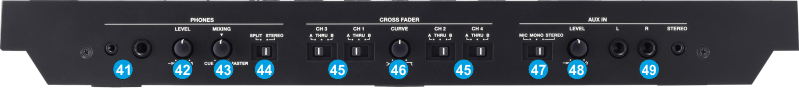
PHONES INPUT: Connect a pair of Headphones to one of the available sockets, using 1/4" or 1/8 " cable/connector for prelistening.
PHONES LEVEL: Adjust the output volume of the Headphones channel (Hardware operation)
PHONES LEVEL: Use this knob to blend in Headphones the audio signal from the Master Output and the Decks that are sent to Headphones Channel via the CUE/PFL buttons. (Hardware operation, not visible on the VirtualDJ GUI). When the knob is at the minimum position, only the Decks that have been selected with the CUE/PFL buttons (at the top panel) will be heard in Headphones. When the same knob is at the maximum (right) position, the signal from the Master Output will be heard in Headphones.
PHONES SPLIT: When this switch is in the SPLIT position, the headphone audio will be "split" such that all channels sent to Cue are mixed to mono and applied to the left headphone channel and the Program mix is mixed to mono and applied to the right channel. When the switch is in the STEREO position, Cue and Program audio will be "blended" together.
CROSSFADER CH ASSIGN: Routes the audio playing on the corresponding channel 1 to 4 to either side of the crossfader (A or B), or bypasses the crossfader and sends the audio directly to the Program Mix (center, THRU).
CROSSFADER CURVE. Adjust the response curve of the cross fader.
AUX IN MIC/MONO/STEREO: Select the AUX IN source, depending on the connected device. Set to MIC If a mic is connected. Set to MONO If you want to input sound in mono. Set to STEREO If you want to input sound in stereo.
AUX IN LEVEL: Adjusts the level of the sound that’s input to the AUX IN jacks.
AUX IN SOCKET: Connect these sockets to a mic or audio device.
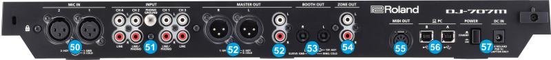
MIC IN 1/2 Connect your microphones here using 3-PIN XLR cables/adapters
INPUT (CH 1–CH 4) These jacks input sound to channels 1–4. The CH 1 and C H2 INPUT jacks support phono input from MM-type cartridges. Set the input select switch of the mixer section appropriately for the device you’re connecting.
MASTER OUT Connect your powered speakers or power amp here. Both XLR type and RCA phono type plugs are supported. The level of this output is controlled by the MASTER LEVEL knob at the top panel
BOOTH OUT These are the output jacks for booth monitoring.. The level of this output is controlled by the BOOTH LEVEL knob at the top panel
ZONE OUT Use these output jacks when you want to send signals to another location independently from MASTER OUT or BOOTH OUT. Connect them to your speakers or recorder.. Use the Utilities Menu of the Roland DJ-707M to define what will be routed to the Zone Output. The level of this output is controlled by the BOOTH LEVEL knob at the top panel
MIDI OUT This connection outputs MIDI messages such as MIDI clock.
USB Use any of the 2 available USB connections to sends and receives audio and control information from a connected computer.
POWER: Use the included power adaptor to connect DJ-707M to a power outlet. Use the Power Switch to turn the unit on and off. Turn on DJ-707M after all input devices have been connected and before you turn on amplifiers. Turn off amplifiers before you turn off the DJ-707M